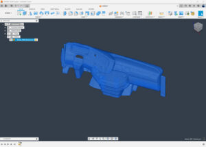
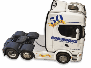
I recently invested in a 3D laser scanner, as this technology has come on leaps and bounds over the last couple of years or so. The price of high quality 3D scanners, irrespective of the type, has improved greatly and continues to do so at an alarming rate.
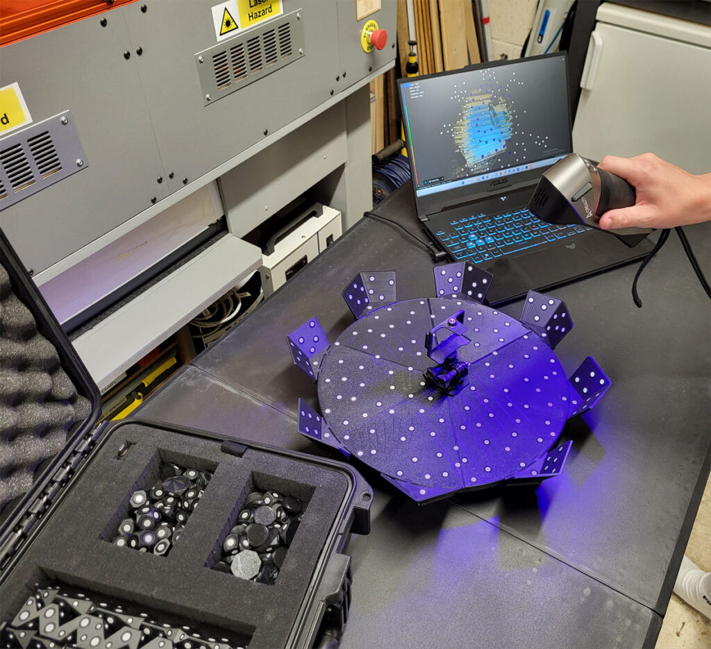
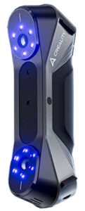
Creality Raptor Scanner
I opted for the Creality Raptor system, although there are numerous manufacturers to chose from. The Raptor includes a combination of NIR (near Infra Red) and Laser scanning modes, the latter of which produces almost metrology-grade scans, with a resolution of up to 0.1mm.
Most 3D scanners, if not all, work on the same principle, by projecting a beam (or multiple beams) of light onto the object being scanned. These beams produce a huge quantity of points in space (known as a Point Cloud). Depending on the size of the object and the selected resolution, tens of thousands or even more than a million points can be produced. This might not be the most technically accurate description, but you get the idea!
I also invested in a new, more powerful laptop, with 24gb of ram and an Nvidia RTX graphics card. 3D scanning requires quite a lot of 'horsepower'!
Laser scanning, which I tend to use most of the time, uses reflective markers to produce the point cloud.
As most of the parts that I scan are relatively small, I produced a turntable (an inexpensive 'Lazy Susan') which is covered in around 180 reflective markers, placed randomly on the platform, as well as on some angled plates around the circumference. These markers are placed randomnly, to reduce uniformity. They can also be placed on the object, but I rarely need to do this.
Creality Scan Software
There isn't much you can do with just the point cloud, as it's just a (huge) bunch of dots in free space. Every 3D scanner is supplied with software that converts this point cloud into something useful. Whilst the following description is very simplistic, it'll show the various steps taken to produce the data geometry that is required for 3D printing parts.
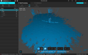
After placing an object on the turntable, which is usually elevated off the flat surface by means of gluing a toothpick on the rear face, the object is scanned, which is displayed in realtime in the software.
The scan changes colour to show the captured data progress, and when object is a solid colour, this means that enough data has been scanned.
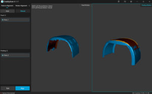
Two or more scans are usually required, as one scan will only generate geometry of one side. So, the object is flipped over and a second scan is done. Most objects will scan correctly with two scans, for example, the front (scan 1) and back (scan 2).
After the raw scans are completed, all data, other than the object is deleted. The software does have both automatic and manual functions for this, although I prefer the manual method, as sometimes the auto function doesn't produce correct results.
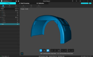
The next stage is to 'fuse' the point cloud into data that can be further processed by the software. Mostly, this is a one-click process and when completed, the 'meshing' process can be done. If two or more scans have been made, these have to be 'aligned' or merged together. Again, very often the complex algorithms in the software are clever enough to do this automatically, and combine the two scans into one object. A manual method is available, where three or more points on each scan are selected, then the software computes the alignment (merge).
After 'fusing' and 'aligning' have been carried out, the geometry can then be exported as an STL (STereoLithrogrophy) file.
3D printers use the STL format, so these files can be directly imported into the 'slicing' software. However, some scanned objects require further processing or modifications, which can be carried out in Autodesk's Fusion software.


