As well as model trucks and trucks in general, my other main interest is CNC machining and factory automation. Here you'll find information on the systems I have in my workshop, including the main CNC machine, electronics controller and software associated with these.
I have recently updated the electronics control and software for the CNC machine. Details are now shown below.
In the past I have had three different CNC machines. Starting with a very basic, mainly home-made machine with a relatively small footprint. This was a good starting point, as it proved that even a very basic setup could give reasonable results.
The second machine featured a larger machining area and was the basis for the third and current setup, having had aluminium profiles as the main construction along with 'proper' CNC movement hardware.
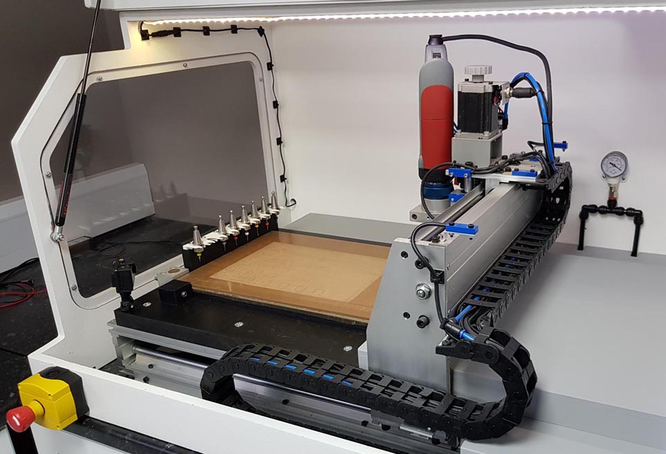
Based around the popular Chinese-manufactured 6040 machine which was purchased with only the mechanical parts and didn't include the motion hardware and controller, as these were migrated from the previous machine. Whilst these Chinese-supplied machines are often dismissed due to quality, I have been more than satisfied with the capabilities of a relatively inexpensive setup.
Upon receiving the machine the first thing I did was to check the main assembly of the mechanics, such as squareness and bolt tightness. I then migrated the main movement hardware from the previous machine, including the three stepper motors, Kress spindle and various other parts. New cable chain, together with mounting tracks were then fitted to the X and Y axes. A cabinet was then drawn up in CAD and produced at my company facilities, where I have the luxury of three large-format Multicam CNC machining centres. Whilst this cabinet isn't entirely needed, it certainly keeps the noise levels to a minimum as well as reducing the dust in the workshop. Plus it looks cool!
A new tool rack was constructed for the automatic tool-changer which is a Kress 1050 spindle coupled to a pneumatic drawbar purchased from Sorotec in Germany. This is an expensive piece of hardware, especially for hobby-use but once installed is a great feature of the machine. The tool rack is now 7 way instead of 8, due to a purchasing a revised ATC which is slightly wider than the original.
The Creality CR10 printer was used to produce the new tool rack and this version is split into two sections due to the limits of the printer. I mounted lightweight springs between the actual tool holder 'cups' and the supports, which allows for slight vertical movement when tool-chnaging.
The automatic tool-changer uses SK15 tool-holders with a collet size of ER11. The drawbar system is pneumatically powered, controlled by software via a custom-made controller. A vacuum bed with sacrificial MDF spoilboard makes easy hold-down of materials. Machining dimensions are 300mm (X) by 210mm (Y) by 55mm (Z), which I've found to be plenty big enough for my modelling needs, considering that the majority of the parts I machine are thin plasticard sheets.
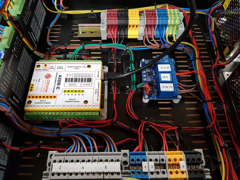
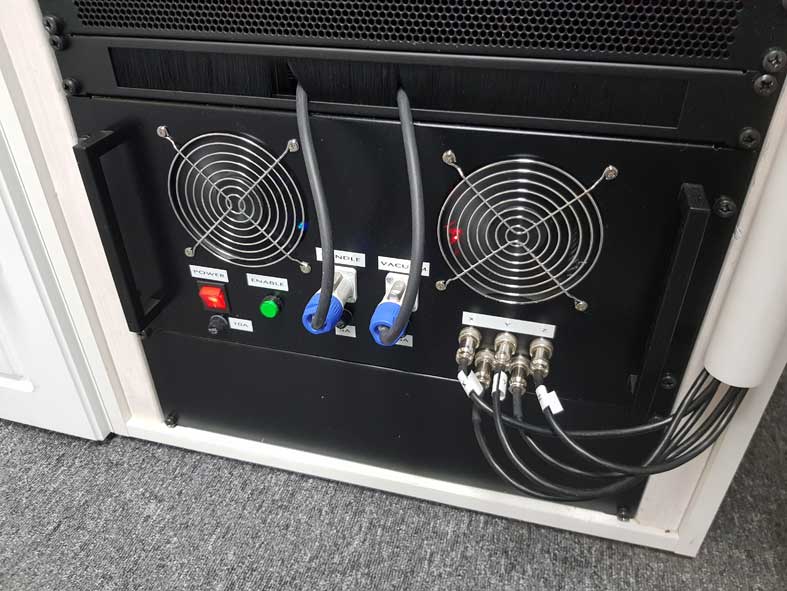
A new electronics controller was also constructed, as the new software update connects to the CNC via ethernet, not the out-dated parallel port. This was the main reason to upgrade the electronics controller and software, as the LPT port is somewhat unreliable. The construction of the new controller cabinet is shown below, all fabricated in my workshop.
Control is now handled by UCCNC as I decided to migrate from Mach3. The graphical interface had to be completely redesigned by myself, using UCCNC's built-in editor. Every button, section panel, and labels have been produced in Photoshop Elements and the master image file contains over one hundred layers to maintain easy editing. The display screen is an Iiyama 22" touchscreen, used in portrait orientation.
I recently updated the screenset to give it a more modern appearance. The keyboard at the bottom of the screenset is not part of UCCNC but a separate program - Comfort On-Screen Keyboard. Whilst relatively time-consuming, each virtual keyboard can be customised to suit individual needs, so I created the orange 'button' images to match the CNC control interface.
Click to see a larger image.
There are five basic sections to the controller interface...Axis DRO's (Digital Read Outs), Toolpath Display, G-Code Display, Tool Management and Feed Rate settings. Also included are controls for additional relay-powered accessories such as ATC drawbar, Air Blow and Vacuum Pump. An Auto-Tool Length Sensor is fitted close to the tool holder bank. This automatically measures the length of the selected tool in relationship to the height of the spoilboard. Again, this is controlled by buttons on the graphical interface. Once the seven tools have been 'length' set, the G-Code automatically selects the relevant cutters.
There are basically three stages in producing parts on the CNC machine. Firstly the drawing is produced to the correct dimensions in 2D using Draft-IT Pro. Layers such as Contour, Engrave, Pocket and Drill are set in the 2D file. Secondly, the toolpath required by the CNC machine is produced in SheetCam, a very simple but powerful programmer for 2D G-Code.
Thirdly, UCCNC is required to control the CNC machine itself. It takes the G-Code generated by SheetCam and produces all the movement, tool-change and suchlike.
